11.4 DESIGN OF REACTION CONTROL ENGINE SYSTEMS
Spacecraft Attitude Control Requirements
Spacecraft attitude control requires the application of torques about the three axes (yaw, pitch, and roll) passing through the vehicle's center of mass. The problem of attitude control implies rotation and/or stabilization of the vehicle about these axes. Its operation consists of two main phases: (1) Rotation of the vehicle over a given angle, within a specified time (2) Stabilization of the vehicle in a required position, within acceptable tolerance limits
The position of a vehicle, if left uncontrolled, may not be the one required for efficient use of its main propulsion system. For example, a spacecraft may have to perform a series of tra- jectory correction maneuvers, for which it must be oriented properly.
Another example is spacecraft separation from the launch vehicle, during which momentums may be imparted which require correction for proper orientation.
Ideally, when a spacecraft is oriented at some attitude, it should remain there indefinitely. This, however, is not the case, because the spacecraft is continuously subjected to small external and internal forces which will cause it to drift off the desired position. An attitude control system must function to counteract all disturbing torques. It could be of either a continuous, or of an on-off type. Practical considerations tend, in general, to favor the latter. The attitude control system itself contains certain nonlinearities and nonideal conditions. In actual operation these inherent nonlinearities cause the vehicle to settle in a periodic motion about a reference point. This motion is represented by a closed curve in the phase-plane and is termed the "limit cycle of operation."
The problem of attitude control, then, becomes twofold: (1) what is required to rotate the vehicle through a given angle to some new attitude, and (2) what is required to maintain the vehicle in this attitude. The energy requirement to accomplish these two basic maneuvers can be calculated, and total attitude control requirements for any space mission can be computed, by simply determining the total number of times that these two maneuvers occur.
Of the various attitude control systems, the reaction systems are the most versatile and provide a wide range of torque, up to high levels. They are universally applied to manned spacecraft and in large unmanned vehicles.
Operational Modes of Reaction Control Systems
If any reaction control system, the amount of thrust delivered on command must be very precisely controlled, if overshoot or undershoot and hunting are to be avoided. Three basic operational modes are available:
- On-and-off, or "bang-bang" control.-This "multiple start" system operates intermittently as long as necessary at its rated thrust level. If the on-and-off command signals are given as a function of sensed position error only, the system would tend to be unstable because of the timelags that are present in all real systems. This situation can be corrected through the use of control systems which utilize both position error and rate of error change to time the on and off command signals.
- Proportional control.-The operating thrust of thereaction control system is varied according to the sensed error signals.
- Repetitive pulse control.-This type of system needs only position error sensing and uses a system which delivers thrust in a continuous series of accurately reproducible impulse bits to assure orientation and stabilization of the vehicle. The optimum thrust pulse outline should be a square-wave. Control may be achieved by modulating pulse width, or the frequency of a fixed pulse width, or by combining both methods.
Selection of Reaction Control Engine Systems
For reaction control engine systems, both liquid monopropellants and bipropellants have been used. The selection of an optimum system for a given mission is based primarily on total systems weight (including propellants) versus total impulse. As mission time increases, so does the propellant and tankage portion of the total systems weight, while the weight of nozzles, valves, and plumbing remains fixed. A comparison of two reaction control systems of different fixed weight and specific impulse may show the lower fixed-weight system to have an overall weight advantage, despite a considerably lower specific impulse. However, sometimes the lower fixed-weight system cannot be used, simply because it has not enough thrust or cannot be operated more than a specific number of cycles.
If total impulse is the variable and total systems weight the evaluating criteria, a plot of total systems weight versus total impulse can be used to compare competitive systems. If thrust and number of restarts (operating cycles) are also factors, added dimensions in presenting the comparison are required. Based on the selection criteria of minimum total systems weight, the three major factors to be considered as independent variables for different space missions are total impulse, thrust level, and number of cycles. Selection of a reaction control engine system is largely dependent on these three requirements, in addition to reliability considerations. Other important factors are performance tolerances, maximum impulse per cycle, space storage and environment, systems integration, and logistics.
For monopropellant reaction control systems, the system vacuum specific impulse varies from 140 to 165 seconds for 90 percent , and from 200 to 230 seconds for . For bipropellant systems using Earth storables or cryogenics, the system vacuum specific impulse may be estimated by applying an efficiency factor ranging from 90 to 94 percent for steady state, and from 80 to 86 percent for transient operation (less than 25 milliseconds pulse width), of the ideal specific impulse values given in table 11-1. The 90 percent systems are applied up to a maximum total impulse of about 50000 lb -sec and the systems to the same or somewhat higher values. Beyond this level, the hypergolic Earth-storable bipropellant systems, which are in the majority, take over.
Optimization of Reaction Control System Operating Parameters
For most reaction control engine systems, a pressure-feed system using stored inert gas as pressurant is employed because of its simplicity and reliability. After the propellants and their feed system have been selected, parametric analyses of all engine system design variables are performed to establish the minimum weight system, within mission requirements, which still satisfies other important considerations. Major operating parameters affecting systems weight are: chamber pressure, pressurant storage pressure, mixture ratio, and nozzle expansion area ratio.
Chamber pressure and nozzle expansion area ratio are foremost optimization parameters, since the weight of major system components is directly related to and defined by them. Component weights considered in the analyses should include the pressurant and its storage tank, the fuel and oxidizer tanks, and the thrust chamber assemblies. Optimum values for chamber pressure range from 50 to 200 psia , and for nozzle expansion area ratios from to . The optimum mixture ratio depends on propellant type and thrust chamber cooling method used. Optimum design values for inert gas pressurant storage pressure range from 3000 to 5000 psia (using 6 Al-4V titanium alloy forgings as tank material).
Basic System Design for Reaction Control Engines
For and 90 percent monopropellant systems, the propellant tanks can be pressurized by a stored inert gas system, as shown in figure 5-1. The propellant valves are located downstream of the propellant tanks and are used to control the propellant flow to the thrust chamber. In an system, each thrust chamber has its own silver-mesh catalyst, similar to the one in the gas generator shown in figure 4-50. When comes in contact with the catalyst, a hot-gas mixture of steam and oxygen is produced, the temperature of which is a function of concentration and its liquid temperature. For monopropellant systems, some kind of ignition source is usually provided because the catalyst life with is limited. The ignition source could be either an electrical heating element, or a continuously operated nuclear energy device. Frequently, to simplify ignition requirements in a system, a common gas generator feeds several nozzles.
Since the liquid is cool until it decomposes, the components upstream of the catalyst do not require high-temperature materials. However, feedback of heat from the catalyst chamber and the nozzle to other components must be prevented, since it would not only damage these components but could also initiate vaporization or even decomposition of the stored propellant. The system has a temperature advantage (maximum temperature ) over a system using , although the latter has a higher specific impulse. In the system, the high operating temperature of requires suitable materials all the way from the generator to the nozzles.
Figure 11-10 illustrates the basic schematic of a typical reaction control system using hypergolic Earth-storable bipropellants and helium gas pressurization. Two redundant subsystems are provided, each of which is physically and functionally independent. Each subsystem is activated independently by an electrical command signal to the explosive-actuated pressurant-start valves located in the helium pressurization line, and to the various solenoid isolation valves. After passing through a micronic filter, different pressurant-isolation valves, pressure regulators, and the "quad" check-valve assemblies, the helium at the required pressure level pressurizes the positive expulsion bladders in the oxidizer and fuel tanks. Opening of propellant isolation solenoid valves allows the pressurized propellants to flow through micronic filters, distribution lines, and line isolation solenoid valves to the normally closed injector solenoid valves which control the operation of the individual reaction control thrust chambers. The system is shut down by removal of the start signal. This closes the propellant-isolation valves and disconnects the reaction-control injector-valve solenoids from the command system.
A relief valve sealed with a burst diaphragm protects the pressurant tank against overpressurization. A high-pressure transducer monitors helium-tank pressure. In a hermetically sealed system, it could also be utilized to indicate the amount of propellants remaining in the tanks. A low-pressure transducer is located downstream of the helium pressure regulators to detect regulator malfunctions. Relief valves sealed with burst diaphragms are also provided for the propellant tanks to protect them against overpressurization.
Systems Redundancy in Reaction Control Systems
For reliable reaction control engine operation, redundancy may be provided in the following three areas:
- Redundancy within a subsystem.-Several typical examples of redundancy within a subsystem are shown in figure 11-10. Two explosiveactuated pressurant start valves are used in parallel. Similarly, two pressure regulators are used in parallel, pilot selected by a three-way solenoid valve. In each propellant pressurant line, a "quad" check valve assembly is used to insure that propellants which may have permeated through the positive-expulsion bladders will not reverse-flow into the common pressurant line downstream of the pressure regulators. A similar "quad" check valve assembly is installed downstream of each propellant tank to prevent reverse flow of propellants from the other propellant subsystem, or from the main propulsion system.
- Redundancy between subsystems.-Refer again to figure 11-10. Here, redundancy between two independent subsystems is provided by normally closed solenoid intersubsystem-propellant
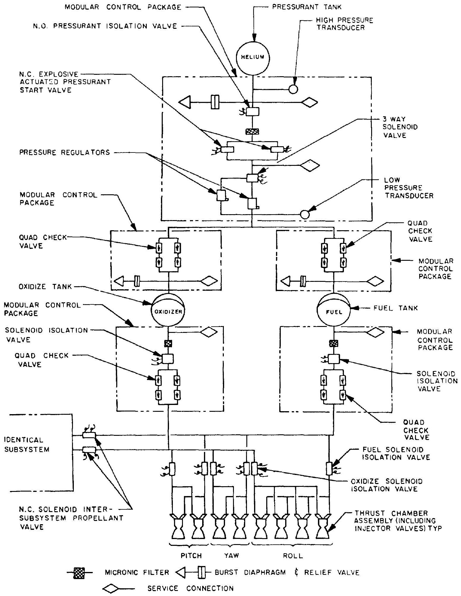 Figure 11-10.-Basic schematic of a typical reaction control system.
valves. If one propellant subsystem should fail, these valves open and connect to the propellant lines of the other subsystems. The distribution line solenoid isolation valves can isolate a group of thrust chambers (pitch, roll, or yaw) should an individual thrust chamber in the group malfunction. 3. Redundancy outside the system.-Redundancy outside the system may be provided by connecting to the pressurant and propellant system of the spacecraft main propulsion system, which must be capable of supplying one or both subsystems with pressurant and or propellants.
Packaging and Installation of Reaction Control Engine Systems
As with spacecraft main propulsion systems, the control components of a reaction control engine system can be modular packaged. The modular packages will incorporate related control components within the same housing (forging or casting), as shown in figure 10-9. Typical modular control packages for reaction control systems are indicated schematically in figure 11-10. The thrust chamber injector propellant valves are frequently designed as an integral part of the thrust chamber assembly (fig. 11-13). All-welded and brazed construction is preferred to prevent pressurant and propellant external leakage.
Figure 11-11 presents the installations of the reaction control engine systems used on a typical manned spacecraft, the Gemini capsule. All
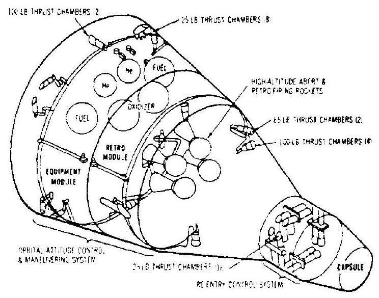 Figure 11-11.-Reaction control engine systems for the Gemini manned spacecraft.
systems are pressure fed and use a propellant combination. The tasks of the Gemini reaction control engine systems built by Rocketdyne are high-altitude abort trim, attitude control in orbit and during reentry, and rendezvous and docking control. In addition, four solid propellant engines built by Thiokol are used for highaltitude abort and reentry retrofiring.
The reaction control engine systems for the Gemini spacecraft (fig. 11-11) consist of- (1) Sixteen 25-pound thrust chambers for reentry control (also see fig. 11-14), consisting of two complete propulsion systems, with a pulsing requirement of 6 cycles/sec and a minimum impulse bit (2) Eight 25-pound thrust chambers for orbital attitude control-pulsing requirement: 6 cycles/sec, minimum impulse bit lb-sec (3) Four 100 -pound thrust chambers for translation control in rendezvous and docking maneuvers-pulsing requirement: 2 cycles/sec; minimum impulse bit lb-sec (4) Two 100 -pound thrust chambers and two 85-pound thrust chambers for longitudinal propulsion-pulsing requirement: 2 cycles ; minimum impulse bit lb-sec The Gemini control thrust chambers are all located inside the vehicle, with the nozzles trimmed flush with the outer skin. Thus, no radiation cooling can be used. All thrust chambers are ablatively cooled.
Design of Reaction Control Thrust Chambers
For systems using hypergolic Earth-storable bipropellants, the reaction control thrust chambers may be effectively cooled by one of the following methods: (1) Ablative cooling (2) Radiation cooling (3) Ablative cooling with radiation-cooled nozzle skirt (4) Ablative cooling supplemented by regenerative or film cooling Other methods, such as regenerative cooling and. film cooling, can probably be used successfully to a certain extent. However, none can compete with ablative or radiation cooling in overall system simplicity, minimum system pressure drop, and minimum performance loss (film or transpiration cooling requires extra propellant flow). Also, the advancement of the state of the art of materials, and of analytical and design techniques, has made both ablative and radiation cooling, rather reliable and practical cooling methods for reaction control thrust chambers.
The design and construction principles for ablative-cooled reaction control thrust chambers are not basically different from those for main propulsion systems. However, the small physical sizes (from 1 - to 100 -pound thrust), and the operational modes (such as the pulse mode) of reaction control thrust chambers, require some special considerations.
For example, a typical roll control thrust chamber is designed to produce thrust ranging from 1.6 to 2.5 pounds at chamber pressures from 80 to 130 psia . The design throat area is 0.0120 in ( 0.124 -inch diameter). This throat diameter should be produced accurately and remain unaffected by erosion during firing. Generally, in small ablative rocket motors, the internal geometry remains essentially unchanged as ablation progresses. The thermal protection in this case is provided by the internal change from the pyrolysis or decomposition of the plastic resin. This yields a porous char layer without any significant dimensional changes. The transition zone between the virgin ablative and the char is referred to as the "char front." The ablation rate, in this case, is not governed by a surface regression, but rather by a regression of the interface between the virgin ablative and the char. However, if highest accuracy is required, throat inserts made of refractory ceramics, such as silicon carbide, and combustion chamber liners made of graphite or ceramics, will further reduce throat-size changes due to erosion and will prevent ablative fluid from being swept downstream from the combustion chamber and deposited in the throat section. Silicon carbide can be machined to rather close tolerances by grinding. The diameter of a throat can generally be maintained with a tolerance of inch.
The methods of determining the char depth of ablative reaction control thrust chambers are similar to those of the larger size chambers. Semiempirical or empirical equations such as equations (4-36), (4-37), (11-1), and (11-2) may be used. However, in the case of reaction control thrust chambers designed for repetitive pulse, or for intermittent operation, the heattransfer conditions may be quite different. Many studies and experiments have been conducted in this area, and theoretical and empirical correlations have been generated.
A study by Lee and Hahn indicates that for repetitive short-pulse operation, the char-front region in an ablative-cooled thrust chamber does not experience appreciable temperature fluctuations, because of the attenuating effect of the low thermal diffusivity of the char layer. The char front region therefore stays at the pyrolyzing temperature during the entire period of cycling. The char regression under pulse operation can, therefore, be treated as a case of continuous firing with effectively reduced gas-side heat transfer. The results show that the char depth based on equal cumulative firing time is a function of percentage of the firing time over the elapsed time. It increases with the decrease of the percentage of firing, to a maximum value several times that obtained with continuous firing. At low percentages of firing, i.e., below approximately 5 percent burn (pulse width/pulse cycle), the char depth drops again, because of the increasing proportion of radiation or convection losses from the outer skin surface of the chamber, to heat influx from the combustion gases. In fact, at some critical pulse mode, the char regression ceases after an equilibrium char depth is attained.
During intermittent, on/off, i.e., multiplestart firings, with off periods in between firings of relatively long durations, the temperature at the char front does not remain at the pyrolyzing temperature all the time. The char-depth progression for a typical multiple-start system is shown in figure 11-12. The ascending straight line represents char-depth progression for a continuous firing ( 100 percent burn). Assume that the first firing cycle was terminated at "a." Since the char layer at this time is at a higher temperature than the pyrolyzing temperature,
[^14]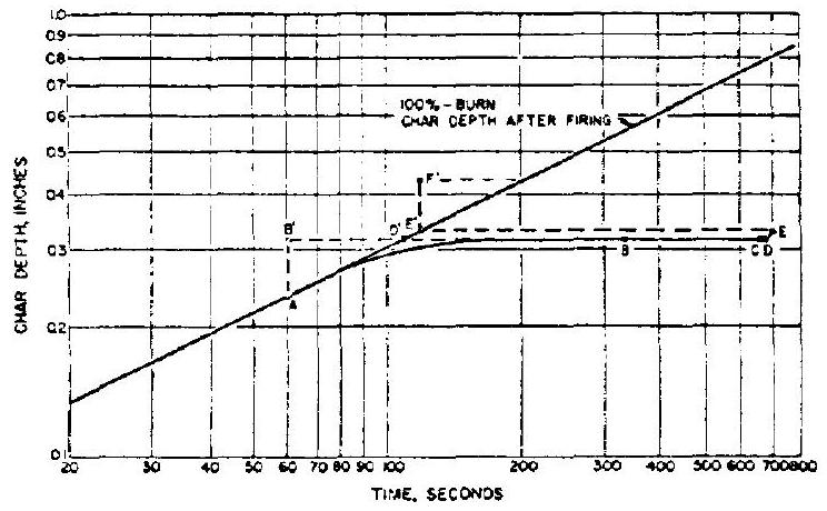 Figure 11-12.-Combustion chamber char depth versus cumulative firing time of a typical ablative-cooled reaction control thrust chamber.
ablation continuous until the temperature at the char front drops below the pyrolyzing temperature (point "b"). When the next cycle starts at "c," the char depth remains constant during warmup, until pyrolyzing resumes through shutoff at "e." The various events may be projected onto the 100 -percent burn line for convenience. The line d'-e' in this case represents the soakback char depth following the second cycle. Subsequent cycles can be treated similarly. Note that in the short second cycle, soakback charring is a multiple of the charring during burning. In general, it can be seen from figure 11-12 that soakback usually consumes a large percentage of virgin ablative and does not contribute to the useful firing time. Even though some char preheating time is gained during the subsequent firing, it could hardly compensate for the loss of burn time which would have been available had the chamber been fired continuously. In this respect, it is desirable to minimize the number of soakbacks, particularly toward the last portion of the virgin ablative.
Combinations of repetitive pulsings and multiple starts can be treated in the same manner as described above, except that the "on" cycles composed of repetitive pulsings will effect a different gradient of the ablation curve, based on the particular percent-burn value, instead of the continuous firing or 100 percent curve.
Figure 11-13 presents the design details of a typical 100-pound-thrust, ablative-cooled, reaction control thrust chamber assembly for hypergolic Earth-storable bipropellants designed and manufactured by Rocketdyne. An optional regen- eratively cooled jacket is provided for extra-long durations (up to 30 minutes). Fuel is used as the regenerative coolant to supplement the ablative cooling. A segmented JTA graphite liner is used in the combustion chamber section; the throat insert is made of silicon carbide. Ablative materials are oriented at and , respectively, at various regions according to structural requirements. Asbestos-phenolic is used for the outer insulation. The injector propellant valves are brazed to the injector, which forms an integral part of the thrust chamber assembly.
Figure 11-14 presents the 25 -pound thrust chamber assembly for a reentry control system, also designed and manufactured by Rocketdyne. Its design details are similar to the thrust chamber shown in figure 11-13. However, no auxiliary regenerative cooling jacket is provided. Rather, a ceramic liner (silicon carbide) is used in the combustion chamber section. The nozzle exit is trimmed flush with the vehicle outer skin.
Total radiation cooling applied to reaction control thrust chambers may pose the following problems: (1) Difficulties when inboard-installation of the thrust chamber is required (2) Thermal shielding requirements for components surrounding the thrust chamber (3) Recrystallization of the chamber construction metals in multiple-start applications (4) Need for a larger thrust chamber, when operated at a relatively low chamber pressure
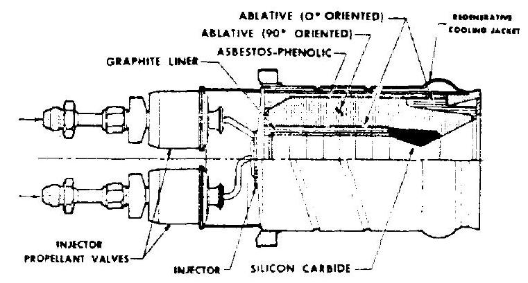 Figure 11-13.-Typical 100-pound-thrust, ablativecooled, reaction control thrust chamber assembly for hypergolic Earth-storable bipropellants, designed and manufactured by Rocketdyne (regenerative cooling jacket optional).
 Figure 11-14.-25-pound thrust reentry control system thrust chamber assembly designed and manufactured by Rocketdyne.
A radiation-cooled thrust chamber, if properly designed and applied, is probably the simplest, lightest, and relatively most reliable. The required working temperature of a radiation-cooled thrust chamber wall could be as high as for Ecrth-storable propellants operated at or near their optimum mixture ratio, and at chamber pressures of 100 psia. Advanced refractory materials such as the 90 percent tantalum-
10 percent tungsten alloy, electroplated with a cermet coating of chromium and zirconium diboride, could be used for the chamber. An alloy of molybdenum and 5 percent titanium, coated with , may also be used.
Figure 11-15 presents a typical, totally radiation-cooled reaction control thrust chamber assembly. It has an integral combustion chamber and nozzle, with a thick throat section. The injector plate can be either bolted as shown, or welded to the chamber. A heat shield is mounted aft of the injector to reduce radiant heat transfer to the injector propellant valves. The shield is shaped to minimize reflection back to the thrust chamber. The shield is attached to the mount structure and is thermally insulated by ceramic spacers.
The injectors for reaction control thrust chambers using hypergolic Earth-storable propellants are usually designed with a conventional fixedorifice, single-ring, unlike-impinging doublet pattern. A splash plate is often utilized to improve performance.
 Figure 11-15.-Typical total radiation-cooled reaction control thrust chamber assembly.
Design of Control Components for Reaction Control Engine Systems
The various aspects of control component design for reaction control engine systems are similar to those for spacecraft main propulsion systems, except that propellant and pressurant flow rates are at much lower levels. For instance, the propellant flow rates of a typical roll control thrust chamber may be 0.0041 to 0.007 (oxidizer), and 0.0021 to (fuel), to produce a thrust range from 1.6 to 2.5 pounds. Besides the propellant injector valves, all other control components, such as pressure regulators, check valves, and vent valves, are similar to those of other systems.
In addition to high reliability and suitability for the space environment, pertinent design requirements for the injector propellant valves of reaction control engine systems are: (1) Fast (as short as 2 milliseconds) and precise response when opening or closing (2) Tight shutoff, with no afterdribble (3) Low power consumption
Most injector valves are solenoid operated. The needle-type propellant valve design shown in figure 7-43 is suitable for integral injector valve assemblies, with both valves actuated by a common solenoid.
Figure 11-16 shows another typical injector propellant valve, designed and manufactured by Rocketdyne. It is used with the reaction control
 Figure 11-16.-Typical injector propellant valve used with reaction control thrust chambers in pulsing applications, designed and manufactur d by Rocketdyne.
thrust chamber assemblies shown in figures 11-13 and 11-14 for pulsing applications. The valve is a fast-acting, solenoid-operated, directactuated type. The propellants flow through the solenoid core at nearly constant velocity, resulting in low-pressure drop. The valve incorporates a hermetically sealed electrical coil, and a metal-ball-type seal. The latter is crimped solidly into the nose of the armature and engages a conical metal seating surface. Positive seating is obtained by lappod fits. The inlet port contains a filter to protect against contaminants. The valve is capable of operating reliably in the temperature environment of space.